2008-12-16
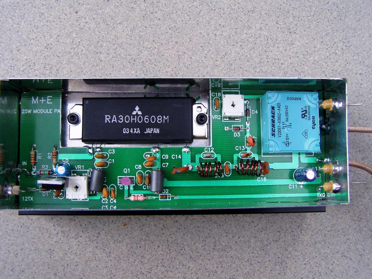
The circuit is quite straight forward and consists of the following subparts:
Drain bias current, IDDQ, vs. gate voltage, VGG.
| VGG [V] | IDDQ [mA] |
| 4,0 | 110 |
| 4,5 | 520 |
| 5,0 | 1550 |
More IDDQ measurements here. I recommend to set IDDQ to 700 mA for linear and mixed modes (SSB, CW and FM) and for FM only to 500 mA.
Fig 1. Power module output power (solid lines) vs. input power and drain current (dashed lines, IDD ). Red lines are for IDDQ = 1,5 A and blue lines are for IDDQ = 500 mA.
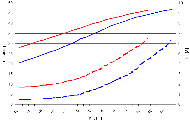
As fig 1. shows the efficiency is quite low in comparison to a discrete transistor PA design. This is quite normal for power modules. As a consequence the heatsink size should be like the ones used for a 100 W brick PA and not as if it was a normal 25 W PA.
Selected dBm and Watt levels.
| dBm | Power |
| -10 | 100 µW |
| 0 | 1 mW |
| 10 | 10 mW |
| 20 | 100 mW |
| 30 | 1 W |
| 40 | 10 W |
| 44 | 25 W |
| 47 | 50 W |
Fig 2. Low pass filter characteristics.
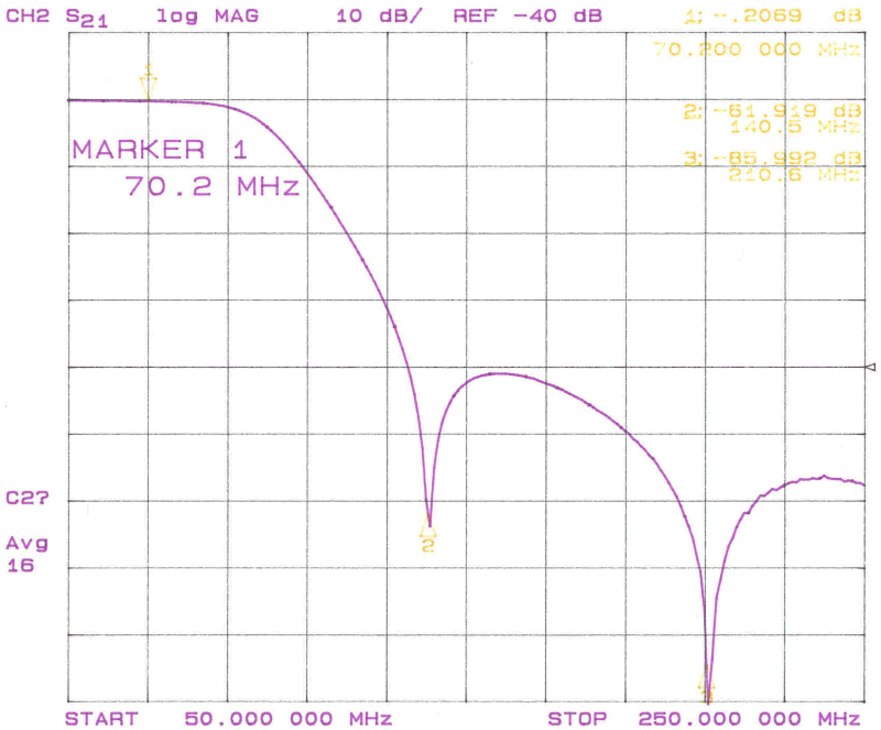
The aligning of the low pass filter is done by squeezing or pulling L3 and L4 but only one at a time. Adjust L3 until the dip is at 210 MHz and similarly for L4 on 140 MHz. The inevitable attenuation in the pass band should not be affected by the tuning of L3 and L4. Otherwise there is something seriously wrong with the coils. In case you do not have the necessary instruments to align the filter apply a small but know signal level at 70 MHz and measure it before and after the low pass filter. The maximum attenuation should not exceed 10%.
Fig 3. Output spectrum of the power module itself at VDD = 13,8 V, IDDQ = 1,5 A and 25 W.
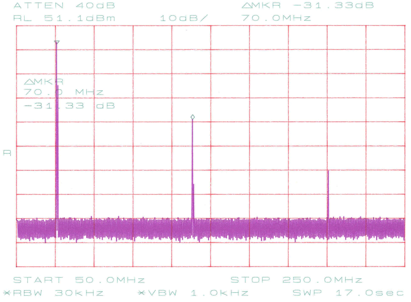
Fig 4. Output spectrum of the power module PA at VDD = 13,8 V, IDDQ = 1,5 A and 25 W.
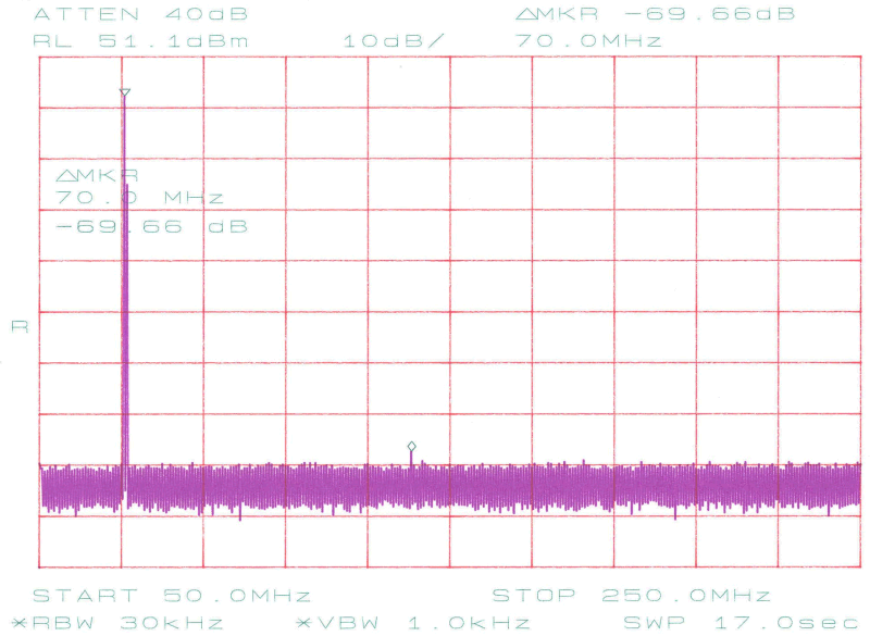
Fig. 5. Intermodulation distortion at VDD = 13,8 V, IDDQ = 500 mA and 25 W PEP. Third order IMD is 24 dB below first order.
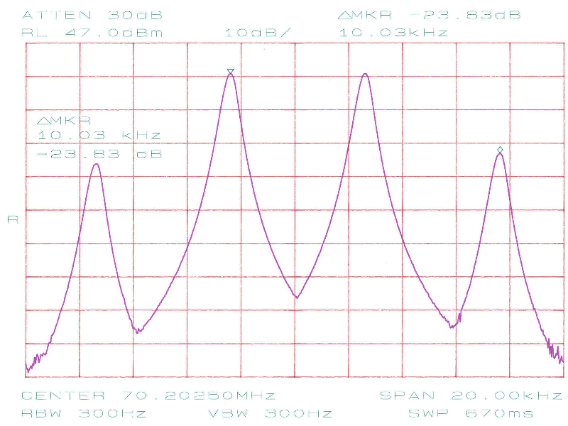
Fig. 6. Intermodulation distortion at VDD = 13,8 V, IDDQ = 1,5 A and 25 W PEP. Third order IMD is 29 dB below first order.
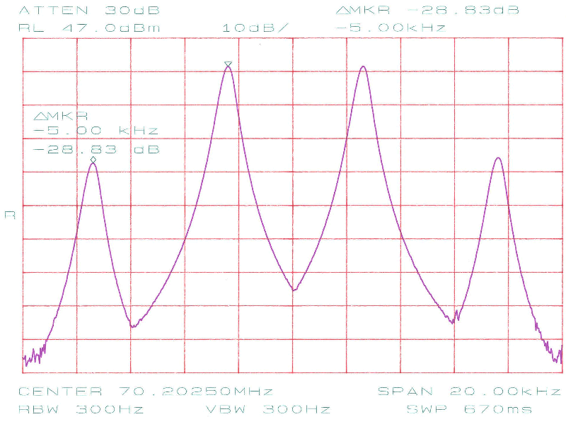
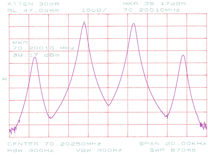
Fig. 7. Intermodulation distortion at VDD = 13,8 V, IDDQ = 1,5 A and 33 W PEP. Third order IMD is 26 dB below first order.
| Resistor | Value |
| R1, R2, R3 | Optional Pi attenuator (see table below) |
| R4 | 390 Ω |
| R5 | 10 kΩ |
| VR1 | 100 Ω, trim pot |
| VR2 | 10 kΩ, trim pot |
All resistors are 0,25 W/0,4 W and metalfilm type.
You have to select the value of R1, R2 and R3 according to your application. Under no circumstances may the input power level to the module exceed 100 mW. If used together with the 70 MHz transverter a 10 dB attenuation is required.
| Attenuation | R1, R3 [Ω] | R2 [Ω] |
| 0 | Do not mount | Short |
| 1 | 820 | 5,6 |
| 2 | 470 | 12 |
| 3 | 270 | 18 |
| 4 | 220 | 22 |
| 5 | 180 | 33 |
| 6 | 150 | 39 |
| 7 | 120 | 47 |
| 8 | 120 | 56 |
| 9 | 100 | 56 |
| 10 | 100 | 68 |
| Capacitor | Value |
| C1, C2, C7, C8 | 1 nF |
| C3, C4, C6, C9, C10, C18 | 10 nF |
| C5 | 10 µF, 25 V, electrolytic |
| C11 | 1 mF, 25 V, electrolytic |
| C12 | 4,7 pF |
| C13 | 15 pF |
| C14 | 27 pF |
| C15 | 56 pF |
| C16 | 18 pF |
| C17 | 1 pF |
All capacitors are ceramic types unless otherwise stated.
| Component | Description |
| D1, D2 | 1N4148 or equivalent |
| D3, D4 | 1N5711, HP5082-2800 or other schottky diodes |
| IC1 | 78L05 |
| IC2 | RA30H0608M |
| Q1 | BC177 or similar |
| Inductor | Description |
| L1, L2 | Ferrite beads |
| L3 | 122 nH, 5 turns, 6 mm inner diameter, 1 mm enamelled wire, 12 mm long |
| L4 | 85 nH, 5 turns, 6 mm inner diameter, 1 mm enamelled wire, 13 mm long |
by Bo, OZ2M, www.rudius.net/oz2m