HV-UNIT
1. Control of the HV Unit:
Switch on the PA, push the red HV knob on the front
panel.
The LED bargraph will sign the actual anode voltage.
On case if we have high voltage voltmeter we can check the anode
voltage on pin
5th of the JP7 connector.
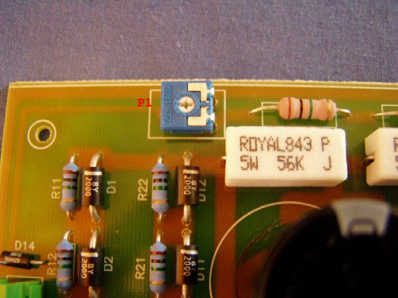
We can calibrate the HV meter with the P1 poti
on the HV unit.
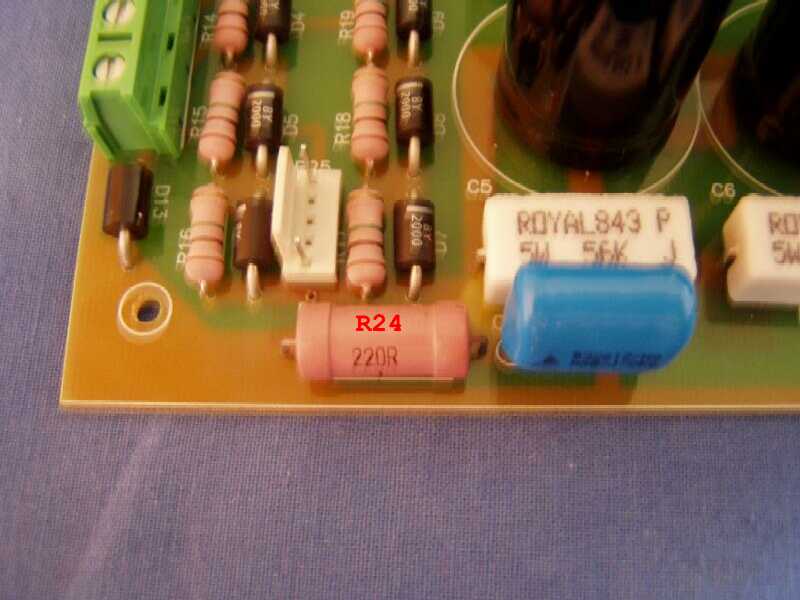
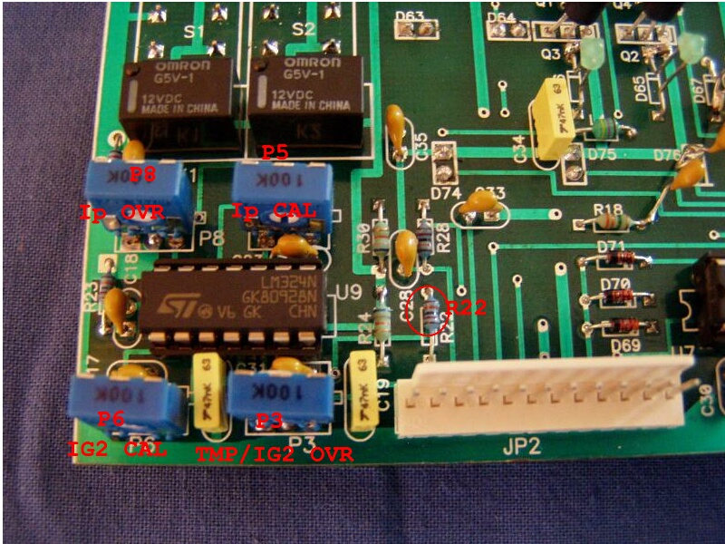
2. MODIFICATION on the HV unit:
- On the
old HV
unit versions we used 10 Ohm/5W resistor on place R24. Change please
this
resistor to 220
Ohm/3W resistor
to better Ip measurment. After replecament have to
recalibrate the Ip meter: Put the PA to TX without drive. (PTT
input Jack is
on
the GND) Check the voltage on the R4 10
Ohm
resistor on the UCU-01 control unit. Set 1.0V on R4 with P6 poti
on the
UCU-01.
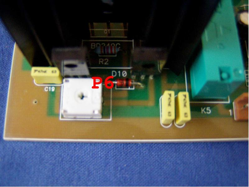
Calibrate the Ip meter with
P5 poti
on the display unit. (This
modification is recommended on the every old HV unit!)
- We moved the HV fuse to rear
panel on
the new models. (Much easy to change the fuse on case any HV problem on
the HV PCB)
Please remove the PCB fuse holder from
the panel.
Remove the wires from original F3 fuse on the rear panel and please
short
the old wires.
Please solder two new isolated
wires to the F3 fuse
holder and connect the ends to the ends of the panel fuse of the
HV unit.
( we use 2 pol. PCB connector on new
versions.) Change the
F3 fuse to 1.25A type.
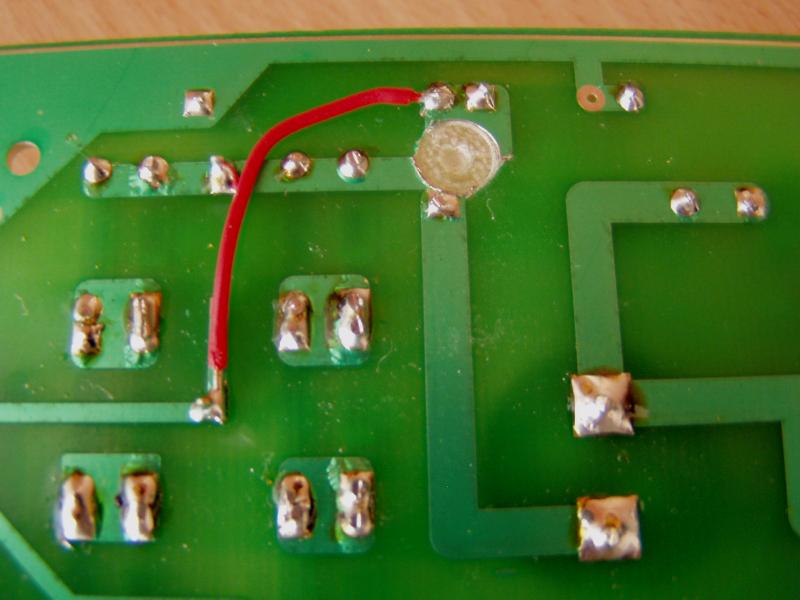
- Cut
the panel line btn -HV point of the rectifer
diodes and the R24/C9 capacitor. Connect R24/C9 with a short wire to
pin 1 of
the
JP7 connector.(after this modification
the HV
meter will not sign if the F3 fuse is broken.)
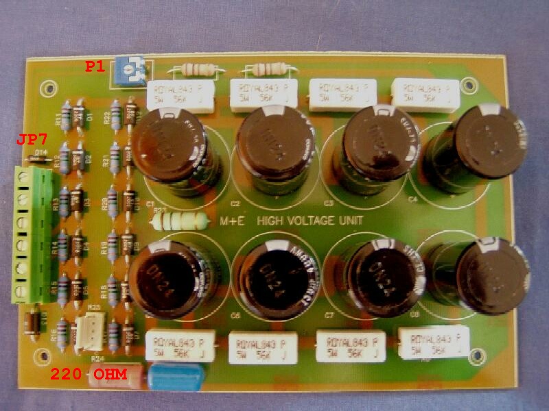
3. VOLTAGES on JP7 connector.
| PIN |
POSITION |
VOLTAGE |
WIRE COLOR |
| 1 |
-B (-HV) |
0- -10V max |
different |
| 2 |
HV/AC |
2100V AC |
different |
| 3 |
HV/AC |
2100V AC |
different |
| 4 |
GND |
0 V |
Black |
| 5 |
+ HV |
+3000V |
white HV cable |
| 6 |
Umeter |
+ 5.6V max |
different |
Mechanics &
Electronics Inc. 1991-2013 All rights is reserved.