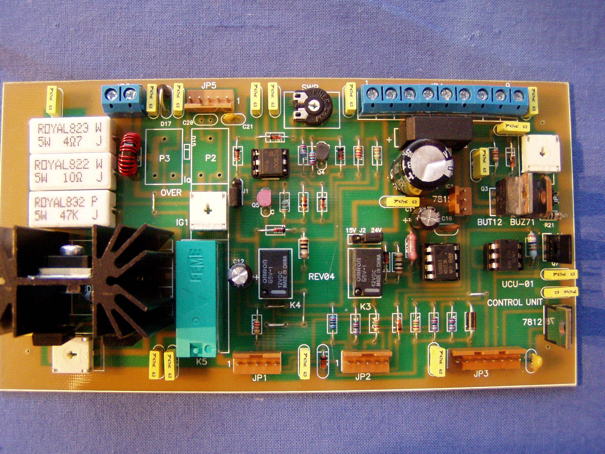
1. CHECKING of the built-in UCU-01 control unit.
Switch on the amplifier and check as follows:
- check the heating time: it must be around 180sec. After 180 sec the
RDY yellow
LED will sign if the PA is ready to work.
- check the 18V AC voltage btn 4-5 pins of JP4 connector. (here must
be18-19V)
- check the following voltages:
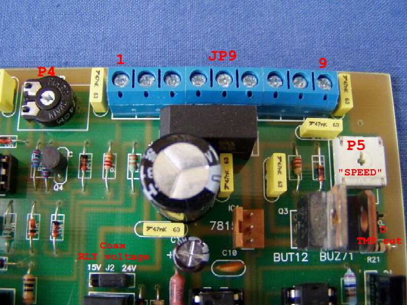
- Please push the TMP knob on the front page of the linear and set
the P5
"SPEED" poti -
up to actual room temperature (20 degr. two green
leds
will lit)
- Set the STBY/OPR switch on the frontpage to OPR position.
- Check now the voltage on the pin 1. of JP1
connector This is the cathode
voltage of the tube, must be >than +40V if the tube receives the
anode
voltage.
- Put shortcut to PTT input of the amplifier: (red RCA jack on the rear
panel)
- The sequencer
unit (only in the new version PA's from 1st Jan. 2009)
will give out shortcuts on the RCA jacks:
- Set now the correct idle current of the tube as follows:
Set finally the P4 poti
to close to full right position. (you can set with P4 te
sensitivity of OVR
operation)
2. Modification
on
UCU-01 panel.
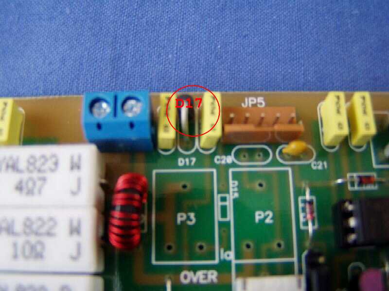
D17 supressor
diode
( 10V/600W bipolar type BZW06-10B) It will save the input of the Ip
meter unit on
case of inner HV arc in the tube.
After any inner arc if
no Ip
measurment check or change this diode.
D18 supress diode (64V/600W bipolar type
built in parallel
with the R1 47K resistor. It will save the Q1,Q7,Q8 transistors on case
HV inner
arc in
the tube.
Some 80x80mm DC FAN produce undesirable wideband
noise in the
RX. To fix the problem put a 100nF capacitor parallel with R21 10
Ohm
resistor ( near of JP7 connector)
3.FUNCTION and voltges of PCB connectors.
JP1. STBY/OPR SWITCH connector
| PIN | FUNKTION | VOLTAGE | WIRE COLOR |
| 1 | CAThode | >40V/RX,~20V/TX | Black |
| 2 | GND | 0 V | Brown |
| 3 | OPR | +15/24V on OPR | Red |
| 4 | OPR | +15/24V on OPR | Orange |
| 5 | STBY | 0 V on STBY | Yellow |
JP2. LED funktion line
| PIN | FUNKTION | VOLTAGE | WIRE COLOR |
| 1 | OVR | +8.2V on OVR | Black |
| 2 | RDY | +1.5 RDY on | Brown |
| 3 | WAIT | +8.2V WAIT on | Red |
| 4 | QRO | +1.5 QRO on | Orange |
| 5 | AIR | +1.5 AIR on | Yellow |
JP3. RLY/PTT out Connector
| PIN | FUNKTION | VOLTAGE | WIRE COLOR |
| 1 | GND | 0 V | BLACK |
| 2 | GND | 0 V | BROWN |
| 3 | RLY + | +15 or +24V | RED |
| 4 | RLY - | max 0.7V on TX | ORANGE |
| 5 | RLY - | max 0.7V on TX | YELLOW |
| 6 | PTT | +15/24V/rx,0V/tx | GREEN |
| 7 | +12V OUT | +12V | BLUE |
| 8 | +15V IN | +15V | CYAN |
JP4. ACC Connector
| PIN | FUNKTION | VOLTAGE | WIRE COLOR |
| 1 | FAULT/SWR | 0 on RX, +3V fault | different |
| 2 | +15V out | +15V | RED |
| 3 | +24V | +24V | RED/ORANGE |
| 4 | ~19V | ~19V AC | GREY |
| 5 | ~19V | ~19V AC | GREY |
| 6 | GND | GND 0V | BLACK |
| 7 | FAN - | 7.8V on 20Celsius | BLACK |
| 8 | +15V | +15V OUT | CYAN |
| 9 | THERM | DIFF | White/red |
JP5. IG1 meter output connector
| PIN | FUNKTION | VOLTAGE | WIRE COLOR |
| 1 | NC. | - | - |
| 2 | IG1 meter out | different | BROWN |
| 3 | NC. | NC. | RED |
| 4 | NC. | NC. | - |
| 5 | NC. |
JP6. -B CONNECTOR
| PIN | FUNKTION | VOLTAGE | WIRE COLOR |
| 1 | HV minus/IP mtr. | 0- -10V max | different |
| 2 | GND | GND 0 V | BLUE |
JP7. TMP meter output.
| PIN | FUNKTION | VOLTAGE | WIRE COLOR |
| 1 | TMP out | 0-1.8V | YELLOW |
| 2 | GND | 0 V | - |
Mechanics & Electronics Inc. 1991-2023. All right reserved.