2013-05-06
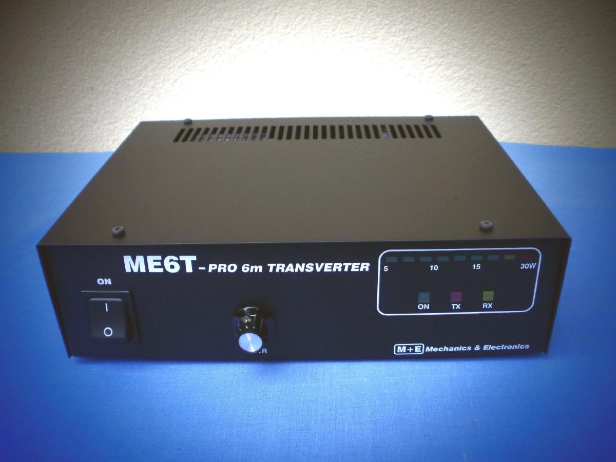
ME6T-PRO 50MHz Transverter
ME6T-PRO High Performance 6m transverter
After the successful ME6-T transverter project we decided to build the -PRO
version of this transverter.
The ME6T-PRO is a new generation high performance transverter with modern 3rd
generation components, has low noise,
very good dinamic range on receiving section and clear and very stable
transmitting signal.
You can find the block diagram of the mixer unit
here.
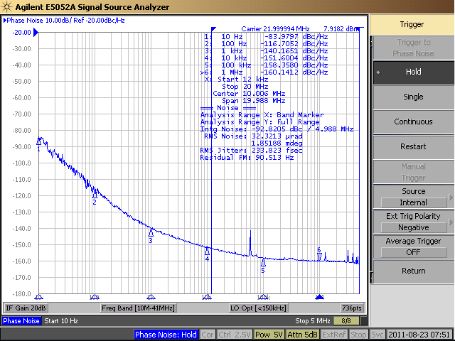
The built in military class low phase noise TCXO provide easy work also on FSK
modes.
The transverter can work between 50-52MHz with low RX NF and high OIP3.
The used Mitsubishi RF module provide good IMD signal and 30W output power.
Special thanks for HA8ET for the RF simulations and the most RF design.
Local Oscillator
The high stability
TC23-5T
type TCXO ( <1ppm btn 0-50degr. C )with
low phase noise give 5dBm signal on
22.000MHz. The TCXO frequency possible
adjust with inner trimmer capacitor(+-2ppm) but it's not necessary because
the stability is better than +-1ppm/ Year.
The output signal of the LO is about +17dBm, it produce the ASB
ASL550
3rd generation MMIC. The clear
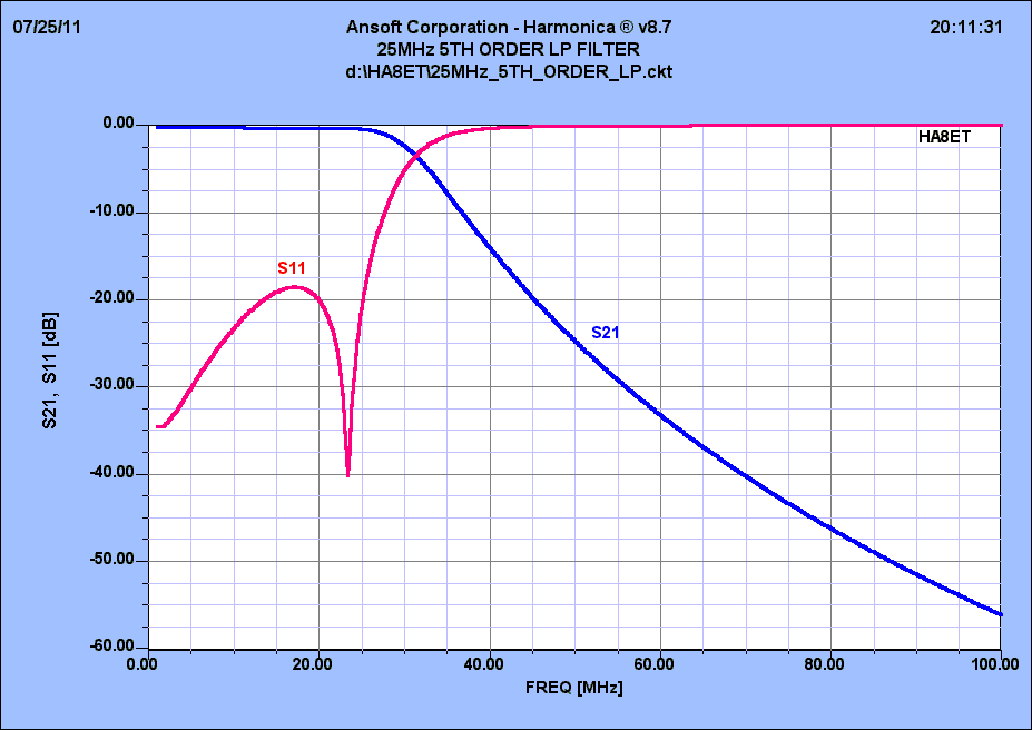
output signal provide the built in 2x 5th LP filter.
The output signal of the LO is clear, the 2nd harmonics is lower than -60dB.
The simulated caracteristics of the 5th LPF filter:
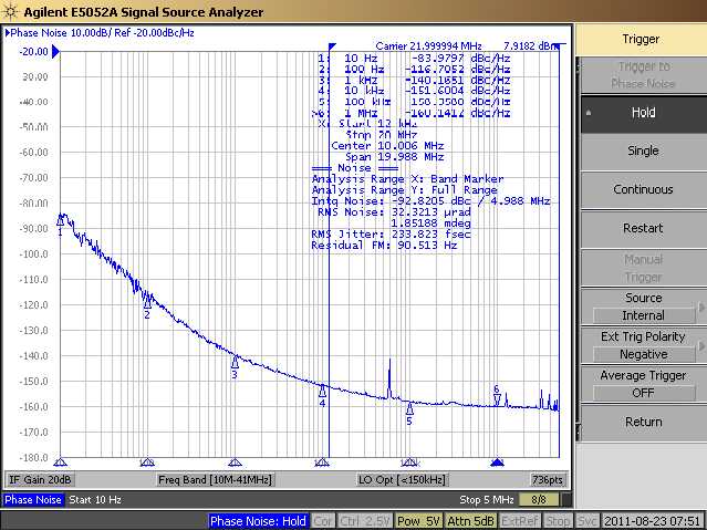
The measured 22.000MHz TCXO phase noise:
The +17dBm output signal can check on M3 measure pin. This signal is attenuated
by -10 and -3dB attenuator to the TX and RX ballance mixers.
We use
SRA1-H type +17dBm RX mixer.
On case the optional +30dBm military class RX mixer (DBM-188)
the AT3 attenuator after TCXO is shorted. The real TX and RX LO signals
you
can check on M2 and M1 points with DC voltmeter.
RX
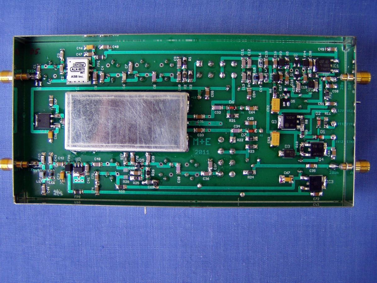
The 50-52MHz input signal passes through the input filter to the input of ASB
ALN0070WT
LNA. The gain is approx. 21 dB,
the noise figure is 0.8dB
the OIP3 is >26dBm! ALN0070WT has an exceptional performance of low noise
figure, high gain, high OIP3, and low bias current. The stability
factor is always kept more than unity over the application band in order system
environment.
Impedance of the MMIC is 50 Ohm both I/O - it provide easy connect to the output
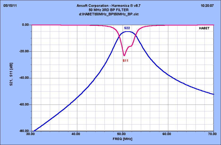
3rd order BPF.
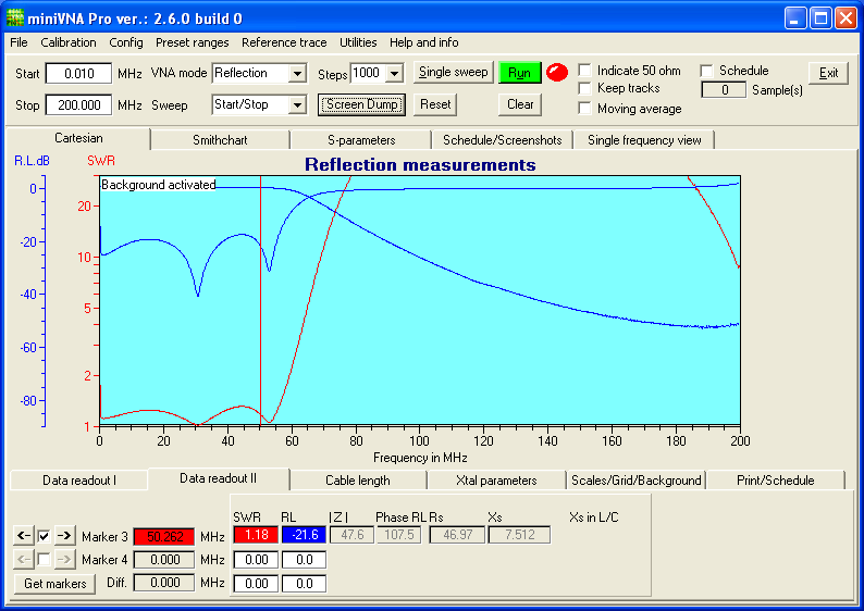
The simulated caracteristics of the 3rd BPF:
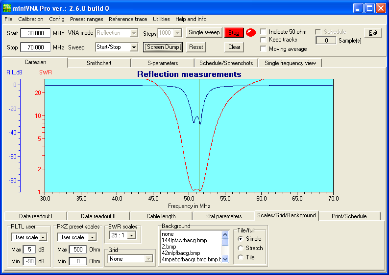
Measured 3rd order BPF:
The 50-52MHz
signal goes through the band pass filter providing a suitable selectivity. The balanced mixer MX1 mixes the
input signal down to 28-30
MHz loosing
approx. 4-5 dB in the process. The IF signal is amplified approx. 10 dB in a low noise
high current
J-FET's (2x J310). The final PI filter
increases the selectivity considerably. The output signal is can set to optimal
value with the RX gain poti.
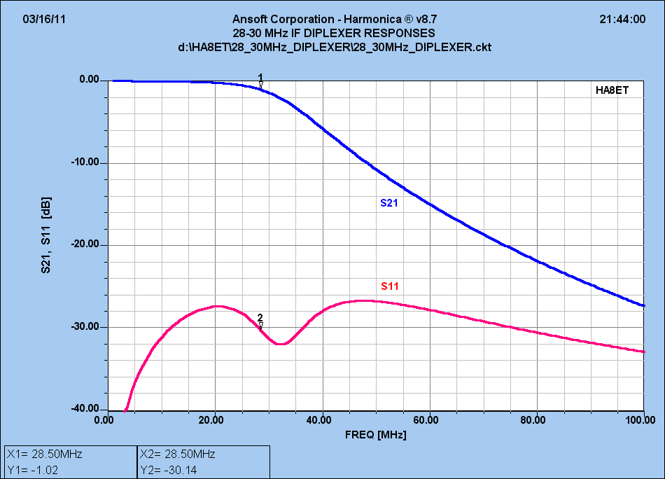
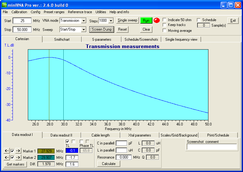
Chracteristics of diplexer unit:
Caracteristics of 28MHz LPF filter:
TX:
The transmit mixer, MX2 only needs approx. min. -10dBm 28 MHz IF signal
from the transceiver. A suitable level can be achieved by adjusting
P2(TX) in the
attenuator. Lot of transceivers has lower or much higher IF
output level. To solve this problem we built in
an
additional jumperable and variable 5W/-20dB attenuator. You can
switch on/off easy the attenuator with different jumpers.
The fine level setting possible with the poti P1 on the attenuator unit across the
slots of the top cover.
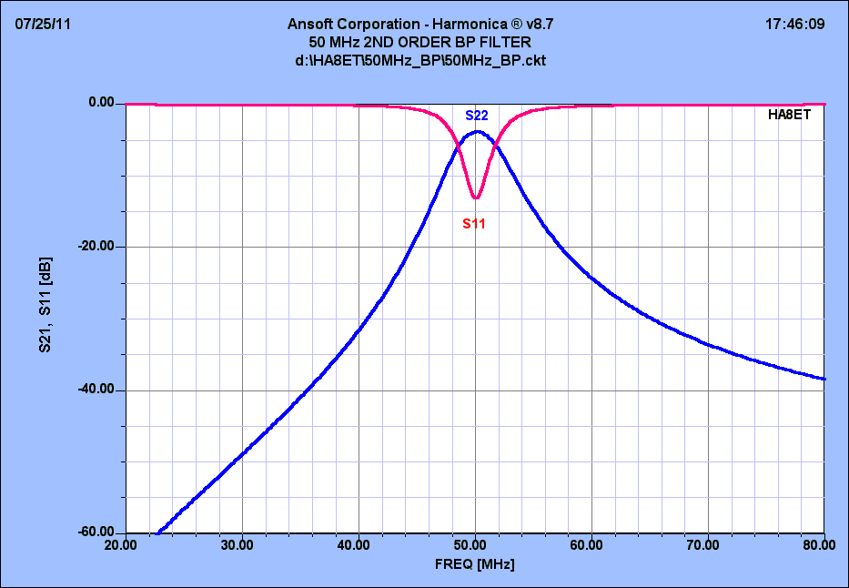
The 50MHz TX signal behind the MX2 mixer is filtered through a
two-stage band-pass filter before being amplified in a BF996.
Simulated characteristics of the 2nd order BPF:
The G2 of the BF996 connecting to the ALC circuit on the control unit and to the
rear panel PWR poti. We can reduce the final output power to about
5-6Watts.
The controlled gain BF996 amplifier continues the final ASL550 amplifier to a level exceeding more than
200 mW. Through the final pi-filter we can
reduce the harmonics of theTX signal.
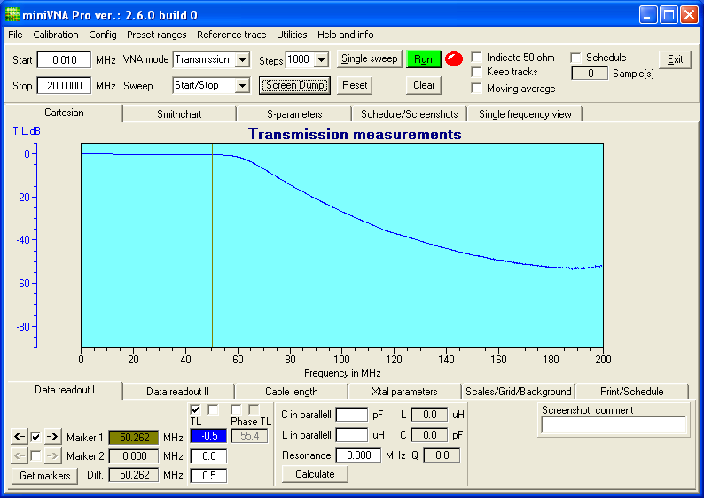
Measured 50MHz LPF:
6m module PA unit
We constructed >25W output amplifier to the base transverter unit. It's
built
with RA30H0608M Mitsubishi module, by Mitsubishi datasheet and
applications.
The output signal of the transverter drives the RF module over -2dB
attenuator. We set the RF module to AB1 class by a simple circuit applicated by
Mitsubishi.
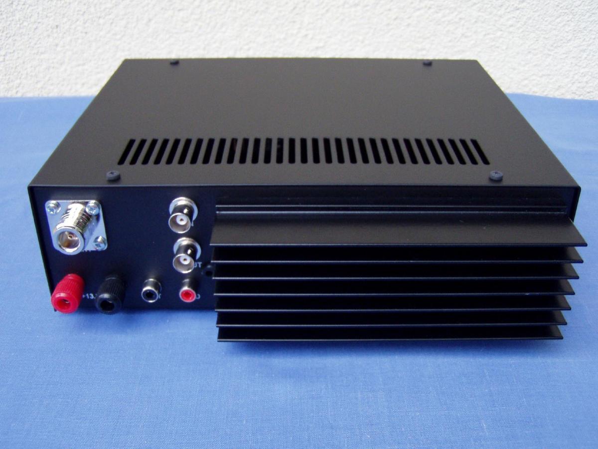
The output signal can reach the 4m UHF type ant connector across a harmonics
filter and a built in G5-V2 relay.
The final unit has MONI output to check the output power connecting to the
control unit LED bargraph PWR meter and ALC circuit.
The PA contains simple temperature sensor to check the temperature of the heatsink.
6m final LPF filter:
CONTROL UNIT
To check the output power we use a LED bargraph unit with LM3419
integrated circuit built on DP6 control unit. On this PCB we found also the
high
current DC relay, the ALC circuit with LM358, and the circuit of the external
fan speed regulator.The external( optional) fan's speed is 50%
when
we are on RX. On case long TX periods when the final module heatsink temperature
is higher the circuit modify the speed of the DC fan's.
The speed is
depend from
the heatsink temperature.We can calibrate the normal fan speed with the P2 poti,
the ALC level with the P3 poti.
The LEG-12 relay is switching the Vpp voltage to the PA unit. The calibration of the
output power is possible with P1 pwr poti on the unit.
NC contact of the relay gives +13.8V voltage across the J6 jumper ( on the
SW/att unit) to EXTRA-6 or similar
mast head low noise preamplifiers.
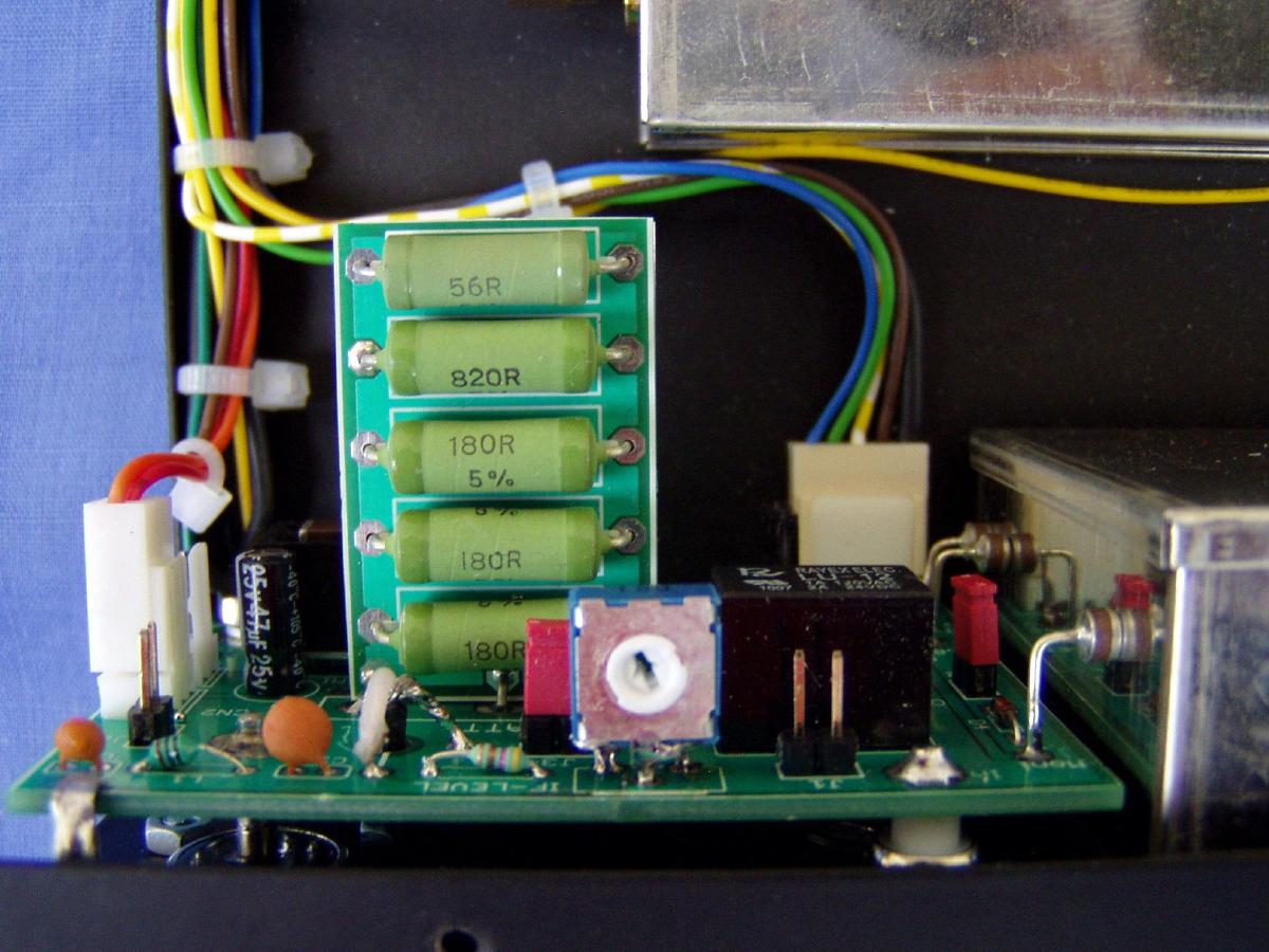
Switch/attenuator panel
Lot of people want to use different IF level transceivers
from
home or / portable. The jumperable attenuator can solve the problem on case high
level or low lever output transceivers.
You can set ON or OFF the 5W attenuator, and you can select easy between single
or dual cable IF operating with the built in jumpers.
The unit consists a switching circuit to the PTT external PA's (red colour
RCA, SND
output,( can switch max +50V,200mA)
The PTT circuit uses two MJD127 for the RX/TX , switching TX when the PTT is
grounded. ( it's on the transverter unit)
It is intended
to the antenna relay and the external PA SND transistor (BD237). The
circuit has sequncer: it's delays the TX key while activates
the antenna relay immediately and also the external PA relay. This means that
the TX output is delayed approx. 50 ms after the antenna relay is activated.
The antenna
relay
of the ME4T-PRO and the external PA switches without any TX signal present.
Position of built in attenuator jumpers
|
Low PWR IF input (-10..+27dBm)
2x IF cable connection |
Low PWR IF input (-10..+27dBm)
1x IF cable connection |
| J1 |
ON |
ON |
| J2 |
OFF |
ON |
| J3 |
OFF |
OFF |
| J4 |
OFF |
ON |
| J5 |
ON |
OFF |
|
High PWR IF input (27..+37dBm)
2x IF cable connection |
High PWR IF input (27..+37dBm)
1x IF cable connection |
| J1 |
OFF |
OFF |
| J2 |
ON |
ON |
| J3 |
ON |
ON |
| J4 |
OFF |
ON |
| J5 |
ON |
OFF |
The J6 is the jumper gives DC voltage to HA8ET's EXTRA-6
preamplifier.
Before set the J6 ON check the compatibility of other type mast head preamplifiers.
The output is +13.8V on RX, the max current is 300mA.
Don't use this jumper , if you havn't got preamp !
If you use single IF cable between your radio and the transverter you
connect it to transverter IFin BNC.
On this case the IFout connector is not in use.
Don't forget to connect the PTT cable between radio
send connector
and ME6T-PRO PTT input! Otherwise the IF power (5W) kills
the transverter
IF output part. The output is saved by antiparallel diodes but it not help on
case high IF powers!
Never use the attenuator more than 5W IF level!
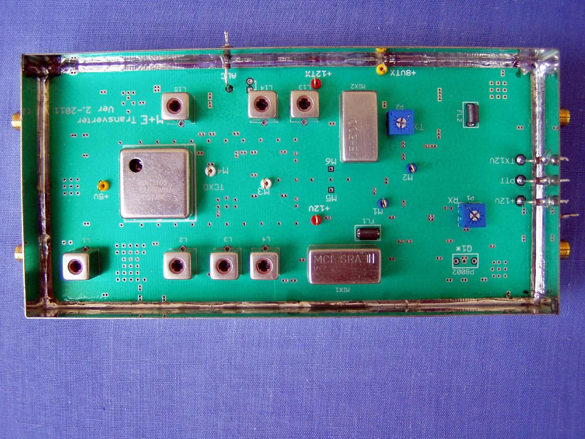
Construction
The base transverter is built on a 1,5 mm double sided glass-fibre epoxy PCB
is fitted into a standard metal sheet box measuring 148 x 74 x 30mm.
PA unit is fitted into 148x55x30mm standard box.Both is fitted with SMD technics.
The external box of the transverter is constructed from 1mm painted iron plate. The
heatsink is 150x55mm ALU heatsink material.
If you use the ME6T-PRO continuously on FSK
mode you can order
optional fan module (2pcs
50x50mm DC fans on holder plate).
No overheating problem on case normal room temperature and CW,or SSB and contest
mode.
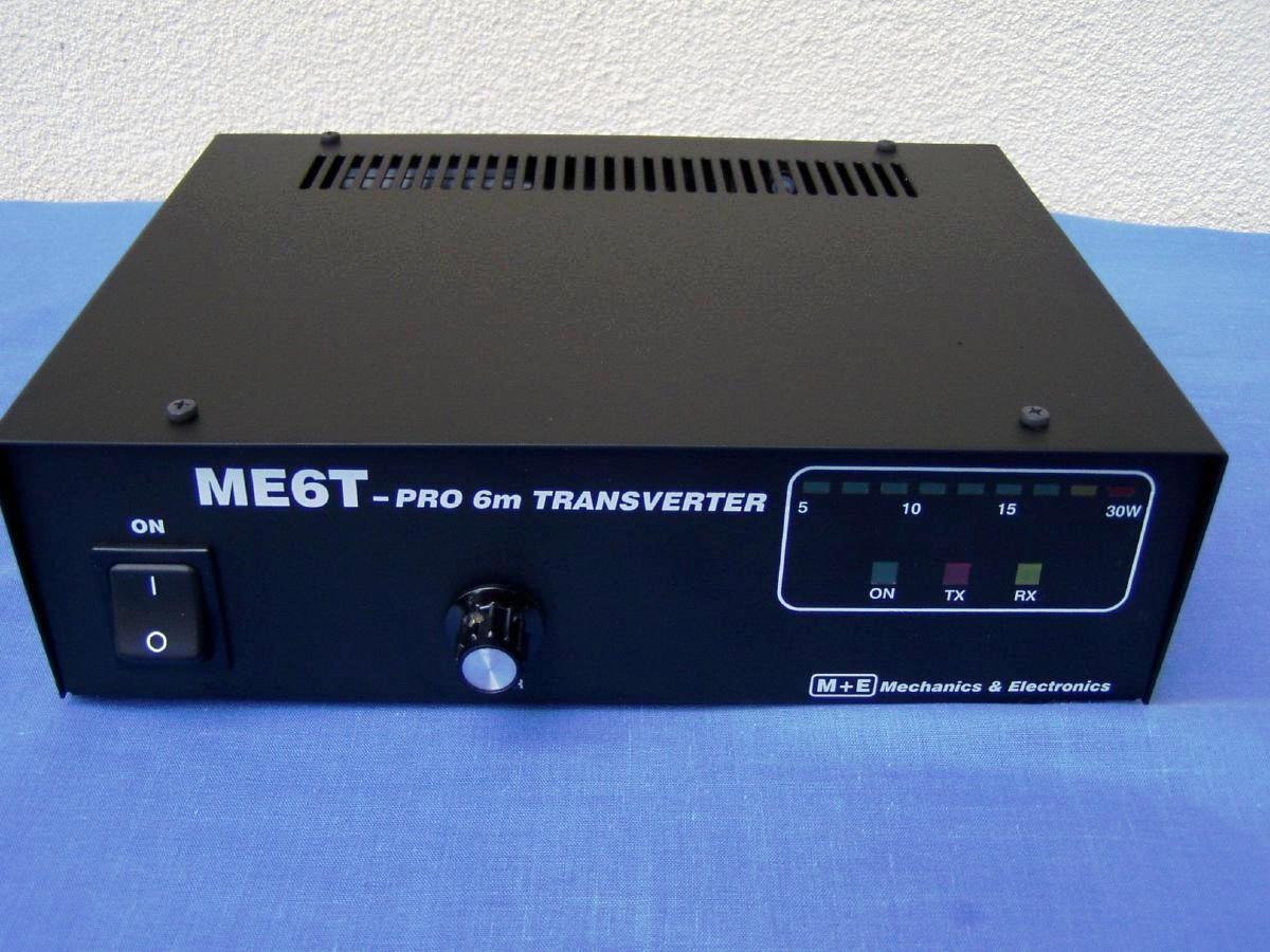
On the front panel we can find the ON/OFF switch, the PWR poti (can reduce the
output power back to 5-6Watts to external PA's) and the LED bargraph
power meter.
Any comments, suggestions welcome!
Mechanics & Electronics Inc. All
rights reserved. 2013